| demonstration system of PIC24F/PIC32MX USB HUB Driver | 2013.9.13 |
[Japanes][English]
1.INTRODUCTIONI made the demonstration system using the USB Host module which had HUB of USB that I showed earlier. I would like to introduce it.
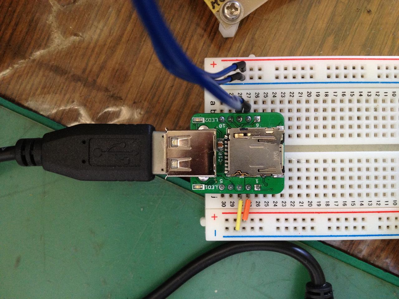 |
I used the 'SBDBT32' board sold by Running Electronics Company for the demonstration system.
This board is convenient to make a USB Host System, because it has a PIC32MX695F512H and a USB A connector. An external interface which has only 10 pins for programmer connection pin and UART connection pin is simple.
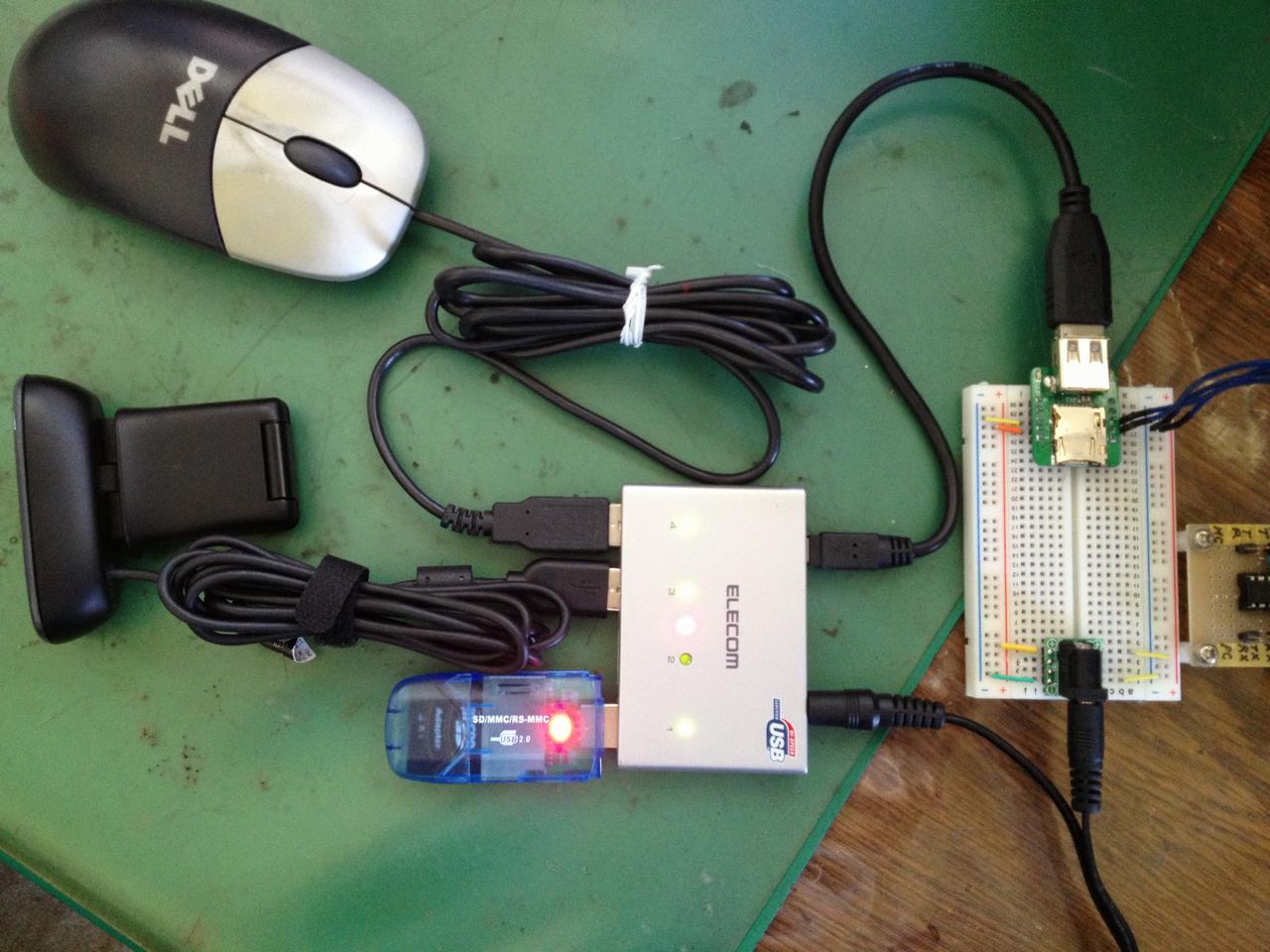
The board is connected to a USB ver2.0 hub which is self-powerd and has 4 ports. 4 equipments of a UVC web camera, a mouse with a wheel and USB Memory disk are connected to it.
Furthermore, it connects SBDBT32 to the PC by RS232. And, a terminal software (e.g. Hyper Terminal, Tera Term etc.) is started on the PC at 115.2Kbps speed.
The demonstration system can check the moving mouse, operate a file in the USB memory and write a camera image into the USB memory.
2. HOW TO USE
2-1. Making demonstration system
Do downloading project file shown below. And, do compile it on MPLAB IDE. Next, Do writing compiled binary file(HEX) in to SBDBT32 using Pickit3.
In addition, it cannot write by the boot loader of SBDBT32. When this demonstration system program was written it becomes impossible to use a boot loader.
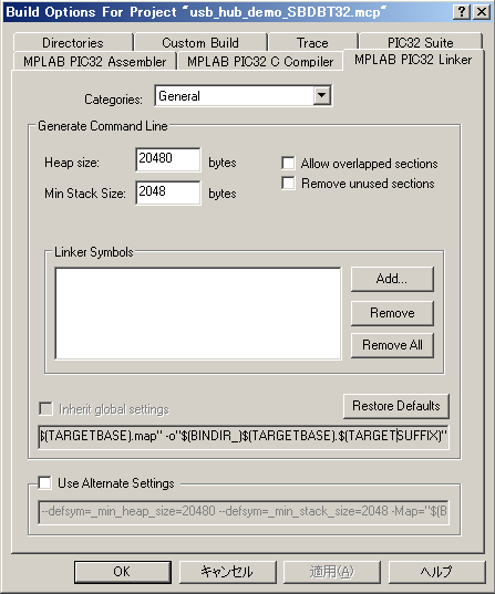 |
In the demonstration system, memory reservation by the call of a "malloc()" function is performed here and there within a program. So It is necessary to specify 'Heap size' of the linker option of MPLAB.
This time, specification as shown in the right is performed.
Incidentally, When I specifyed 'heap size' at 15360 bytes it obtained insufficient memory when it was storing the image data of a camera in a USB memory disk. More over, the system became unstable.
-
Projects file:usb_hub_demo_SBDBT32.zip (last update,2014/1/21)
binary(hex) :usb_hub_demo_SBDBT32.hex
The main program files of a demonstration system are shown below.
| Source File | |
|---|---|
| main.c | demonstration program |
| usb_config.c | USB configuration |
| usb_host.c | USB Host driver which built in HUB driver |
| usb_host_hid.c | USB HID driver |
| usb_host_hid_parser.c | |
| usb_host_msd.c | USB MSD driver |
| usb_host_msd_scsi.c | |
| usb_host_uvc.c | USB UVC driver (made by me) |
| usb_mouse.c | mouse driver |
| FSIO.c | FAT file system |
2-2. Start the demonstration system and devices connection
 |
 |
| A memory, a camera and a mouse are connected to a PIC through a hub | A display of the screen under operation |
First, SBDBT32 in which demonstration system was written is connected to a PC. And, If +5V power is supplied to it, demonstration system will be started.
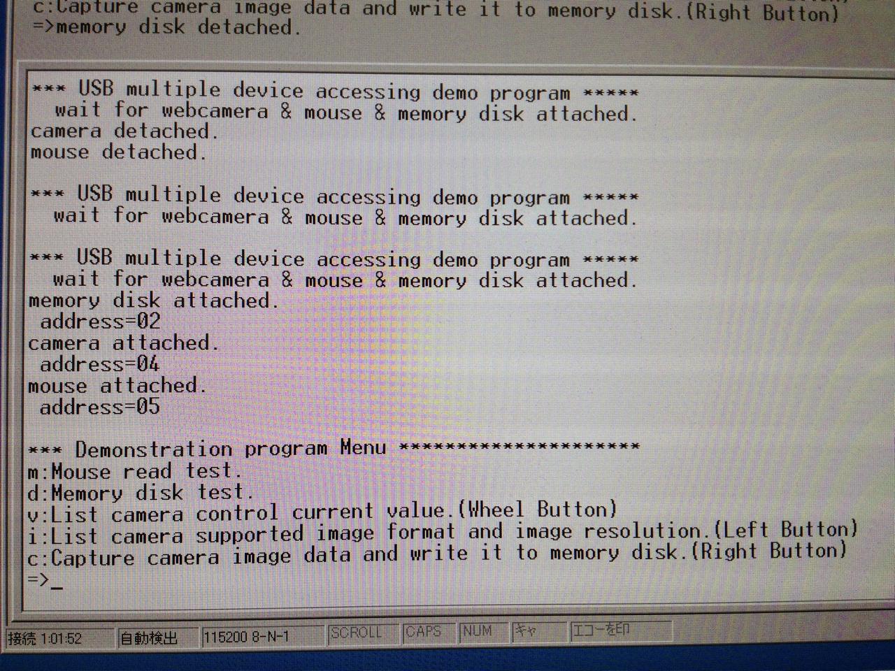
It is a success to start if the following message is displayed on the terminal of a PC.
-
*** USB multiple devices accessing demo program *****
wait for webcamera & mouse & memory disk attached.
Next, a hub is connected to USB port of SBDBT32. Although a display changes nothing only by connecting hub, if a mouse is connected to the port '1' of hub, the following messages will be displayed.
-
mouse attached.
address=2
Here, the following messages will be displayed, if a mouse is once removed and a mouse is switched to the port '4' of hub after that.
-
mouse detached.
mouse attached.
address=5
Below, continuously, if a USB memory is connected to the port '1' of hub and the Web camera of a UVC class is connected to the port '3' of hub, the following messages are displayed and demonstration system can be operated.
-
memory disk atached.
address=2
camera atached.
address=4
*** Demonstration program Menu *********************
m:Mouse read test.
d:Memory disk test.
v:List camera control current value.(Wheel Button)
i:List camera supported image format and image resolution.(Left Button)
c:Capture camera image data and write it to memory disk.(Right Button)
=>
In this introduction, although it was considered as the above connection,
you may connect a camera, a mouse, and a memory to any port of hub in fact.
However, if three devices are not connected, operation of the demonstration system
was programmed to be unable to do.
2-3. operation of demonstration system
It is operated according to the following operation menus.
-
*** Demonstration program Menu *********************
m:Mouse read test.
d:Memory disk test.
v:List camera control current value.(Wheel Button)
i:List camera supported image format and image resolution.(Left Button)
c:Capture camera image data and write it to memory disk.(Right Button)
=>
A mouse can be tested, if a keyboard is typed and 'm' is inputted. Moreover, if 'd' is inputted, the file operation in a USB memory can be performed.
2-3-1. mouse test
The state of mouse is displayed on a screen at the mouse test.
After 'm' is inputted, if the button of a mouse is pushed or it's released or mouse is moved, the following message will be displayed on a screen.
If some keys are typed, it can return to an operation menu.
-
left button on.
right button on.
wheel button on.
move to up.
move to down.
move to right.
move to left.
move to right up.
move to right down.
move to left up.
move to left down.
wheel up.
wheel down.
2-3-2. file operation in USB memory disk
If 'd' is inputted with an operation menu, the sub menu for a file operation will be displayed as follows.
-
*** Memory Disk Test Menu ************************
m: make the directory in current directory.
r: delete the directory in current directory.
c: change the current directory.
l: list file in current directory.
w: text write to a file.
t: read text from a file.
v: file binary dump.
d: delete the file.
f: format a memory disk.
q: quit and return to main menu.
=>
It is operation in which it is not necessary to explain. I want you to actually operate it and to try.
In addition, a LongFilename was not supported but the file name is limited to 8.3 forms. Moreover, there is no distinction of a capital letter and a small letter in a file name. All file names are capital letters. If you need them, do reconstruct system.
If 'q' is inputted, it can return to an operation menu.
2-3-3. camera operation
Next, operation of a Web camera is explained below.
-
v:List camera control current value.(Wheel Button)
i:List camera supported image format and image resolution.(Left Button)
c:Capture camera image data and write it to memory disk.(Right Button)
Selection of operation is possible by the button operation of a mouse other than the method of typing a key.
When 'v' is inputted or the wheel button of a mouse is pushed, the current, minimum and maximum value of the contrast and so on are displayed as follows.
-
Exposure Time(Absolute):
- Cur 338
Min 1
Max 10000
- Cur 0
- Cur 128
Min 0
Max 255
- Cur 32
Min 0
Max 255
- Cur 32
Min 0
Max 255
When 'i' is inputted or the left button of a mouse is pushed, the list of the image format and resolution which a camera supports will be displayed.
-
Supported Format (Number is 1): YUY2
Resolution:
- 160x120 176x144
Resolution:
- 640x480 160x120 176x144
320x176 320x240 352x288
432x240 544x288 640x360
752x416 800x448 800x600
When 'c' is inputted or the right button of a mouse is pushed, read-out of image data will be started from a camera. And whenever it reads the image data of one frame, it is written in a memory disk.
LED of SBDBT32 is blinking during read-out of image data and writing. If some keys are typed or the button of a mouse is pushed, read-out of data will be stopped and it will return to an operation menu.
It's displayed on a screen as follows.
-
Capture image format is MJPEG and resolution is 640x480.
Capture Start!
-- key is inputted or the button of a mouse is pushed --
Capture Stop!
The image format to read is only MJPEG. In the case of the camera which does not support a MJPEG format, the following error message is displayed.
Can't capture image, This camera doesn't support MJPEG image format.Moreover, the default resolution is '640x480'.
(The check of a captured image)
The image data written in the memory disk is stored in the file of the name of CAPTURE.DAT.
The MJPEG image data stored in this file, It can be checked on the screen of a personal computer using the player for Windows "MJPEGPlayerForUVC.exe" which is currently introduced on the support page of SBDBT32 of Running Electronics Company.
|
CAPTURE.avi(189MB) |
In addition, the writing of the image data to a USB memory, Carrying out by the bulk transfer of a 64-byte packet and processing of the adopted file system (FSIO.c of microchip) are slow, The writing of the image data of one frame has taken the time of about 350 msecs, and the picture written in the USB memory is the video of about 3 fps as a result.
Therefor, It will be playbacked by about 10 times of high speeds when it playbacked by MJPEGPlayerForUVC.exe which is playbacking 30fps speed.
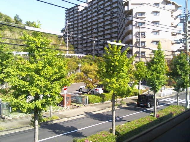
The scenery photographed from the window of the my room using the Web camera "C525" of Logicool is shown in the right. It is playbaked at High-Speed.
3. CONCLUSION
As mentioned above, the example which connects two or more USB devices to a PIC microcomputer using HUB was introduced.
Since USB of PIC is full speed, making high-speed processing perform to PIC has unreasonableness. However, if it is within the limits allowed processing speed, like this example, it can connect simultaneously and can operate two or more devices.
I hope that you will challenge the interesting electronic craft of PIC using HUB.