| Make a Radio Program automatic recorder | 2013.8.23 |
[Japanese][English]
1. INTRODUCTION
Two programs of a radio broadcast are automatically recorded to MD every day from Monday to Friday, and Saturday and Sunday the re-broadcast of the one week using the timer function of a audio component using two minicomponents collected by "Repair of the Junk Audio" until now.
 |
The reason for also using a two component bother is this. Inability to record together one week the two programs in the MD one. In addition, the timer function of the component is so poor, it can not be a variety of recording settings.
I've been recording using two components in as such, but in the MD of 80 minutes, in order to perform the next new recording, it needs to replace with a new one every week. Moreover, much MD is needed if it tries to save the recorded contents at MD.
Then, taking in to PC from MD is performed periodically, and MD is used about so that MD may not be increased, but since taking in to PC from MD turns into analog taking in which reproduces MD, it requires time.
In order to solve this troublesome work, RadioRecorder was made this time.
2. Structure of the system
The radio program automatic recording system was made up using the SD Card, Radio tuner unit and PIC microcomputer. Overview of the system is as follows.
 |
Using a microcomputer, a radio tuner is tuned up and the receiving audio signal outputted from a tuner is taken into the memory inside a microcomputer as digital data by the A/D conversion module of a microcomputer. The voice data which was taken-in is stored as a WAV file in the SD card.
Although 44.1 kHz, 16 bits, and a stereo performed voice taking in and it aimed at about the same quality as CD, since the A/D conversion module of a microcomputer is 10-bit conversion, it is not 16-bit taking in strictly.
The recording schedule for a automatic recording is beforehand stored in SD card as a text file.
In order to control the start of recording, and a stop, the function of the calendar clock was programmed on the microcomputer.
In order to make an accurate recording start control, every hour, we have to correct the time by the time signal of NHK radio broadcast. Thereby, the accuracy within error 1 second can always be maintained now.
2-1. Radio tuner unit
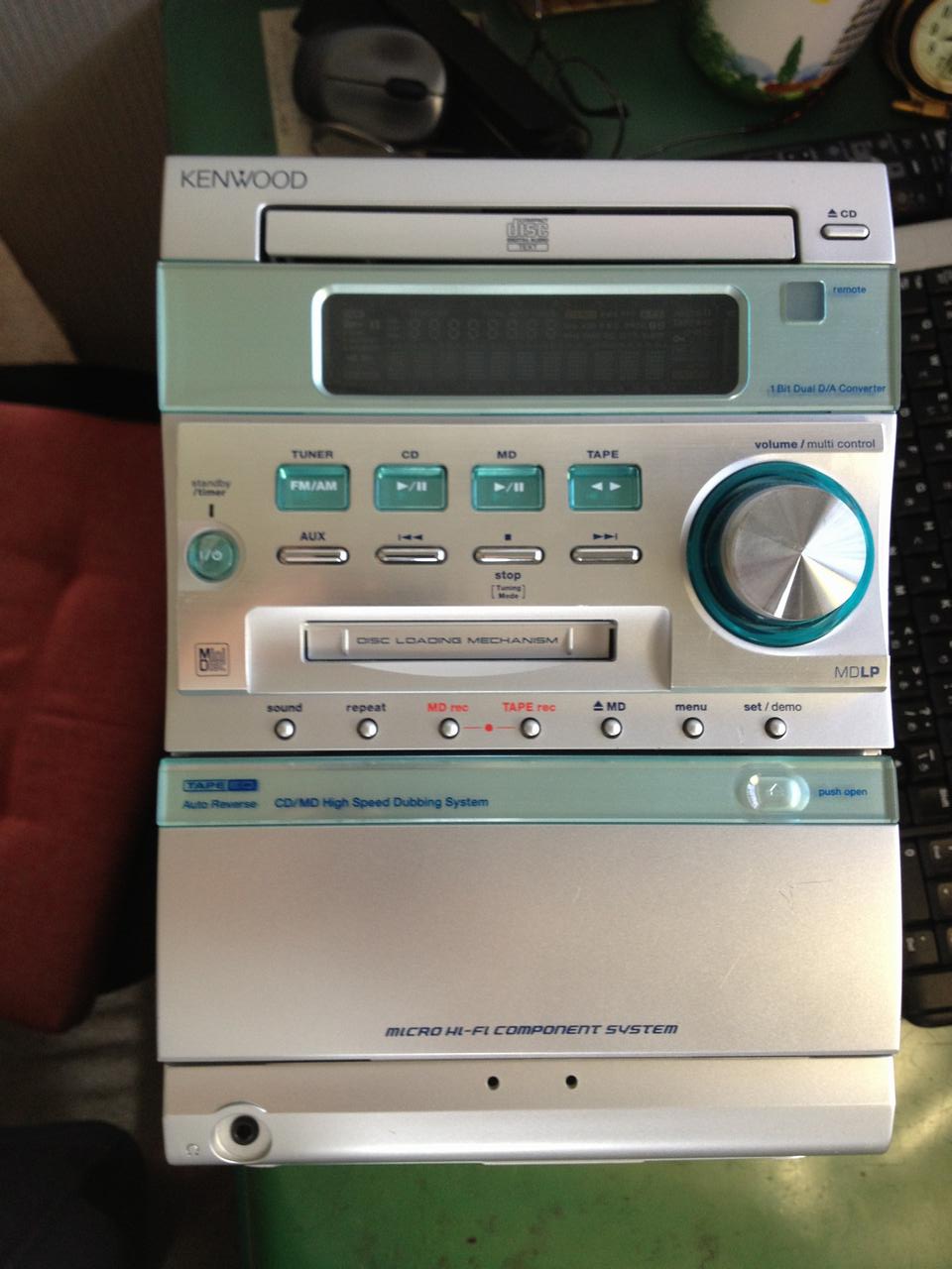
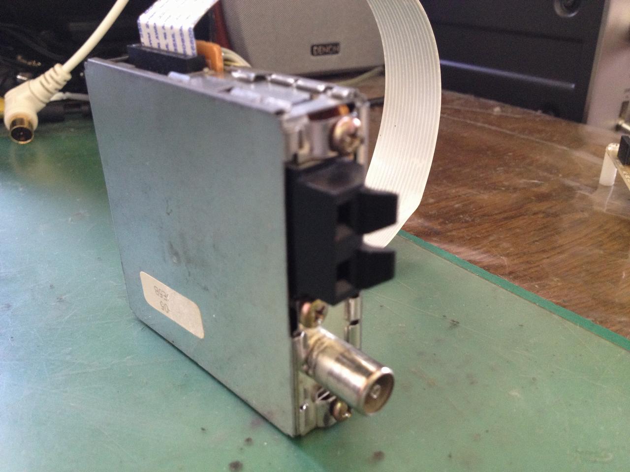
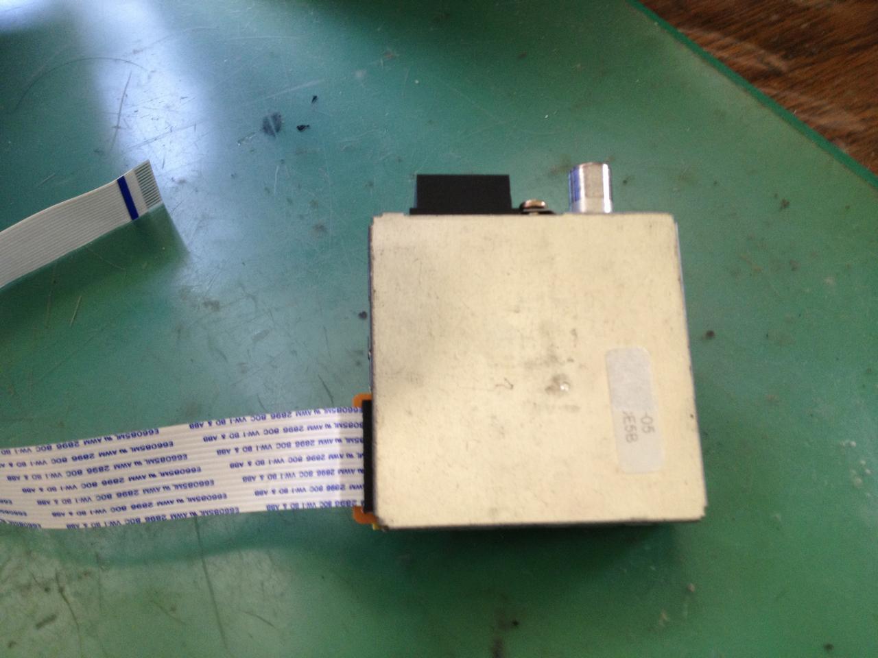
Radio IC for tuners which frequency setting is possible in control of a microcomputer, and can take out an audio signal outside can obtain now easily these days. Although what is necessary is just to have chosen the suitable thing from them, the FM/AM tuner unit built in the minicomponent of junk was used this time.
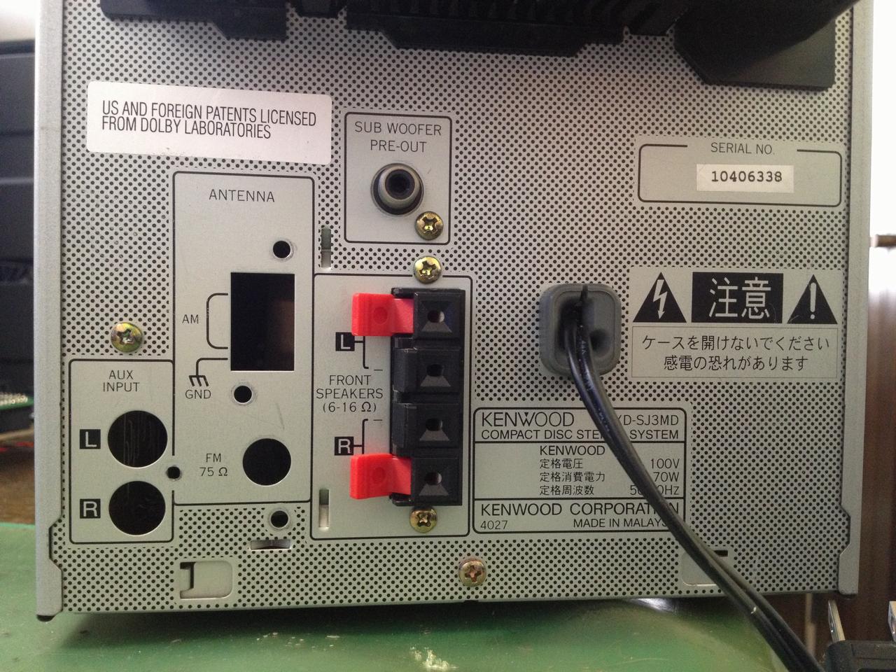
Specifically, it is like this. I was used the tuner unit which was removed from the minicomponent which has name RXD-SJ3MD made by KENWOOD. This minicomponent was bought as an object for part picking. Since this component stereo was only 200 yen, I have bought it involuntarily. There are neither a speaker nor accessories and it is only a main part.
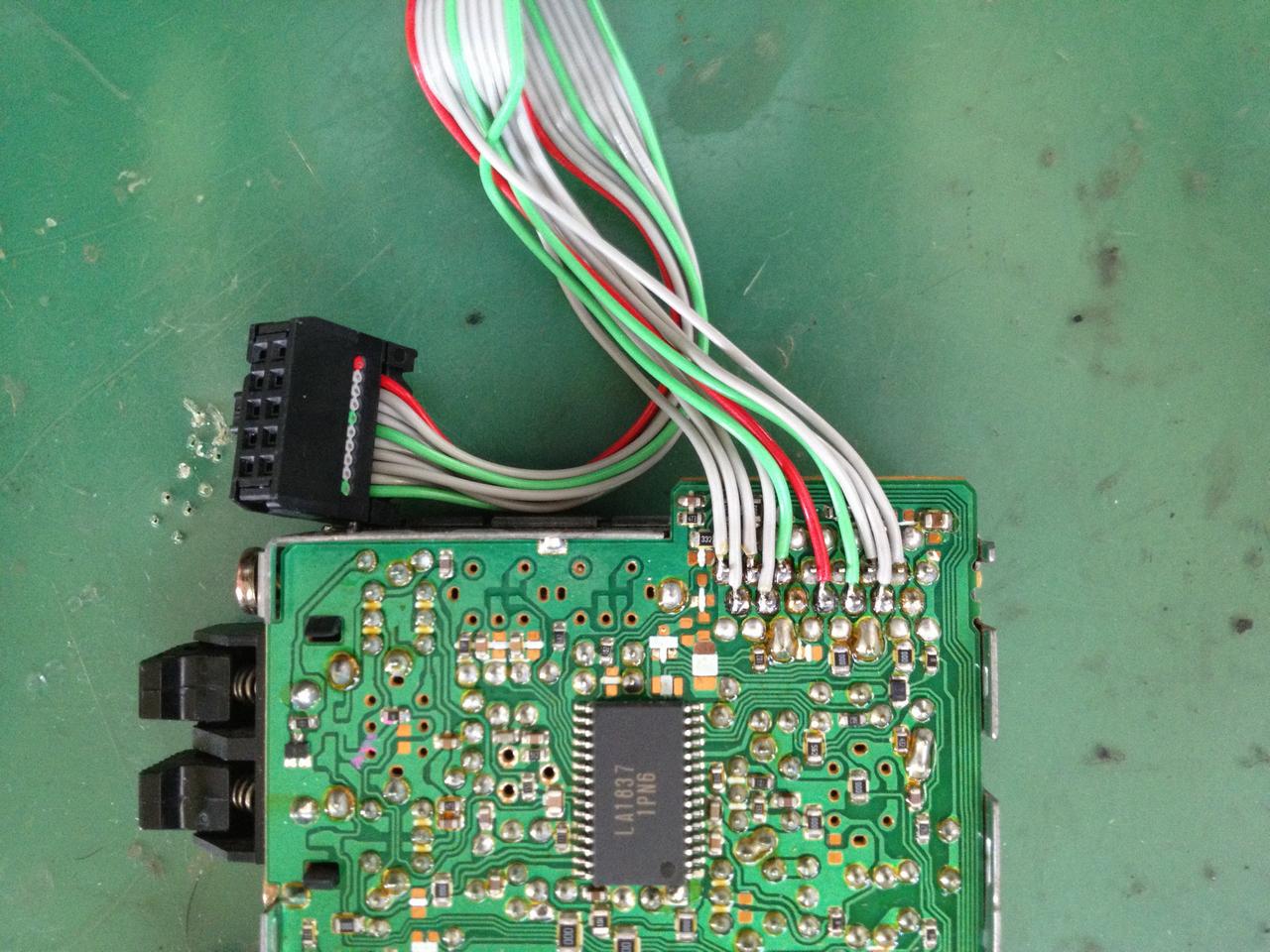
Tuner unit was connected to the main board in the component by the FFC cable which has 15pins. In this case, I soldered the ribbon cable which has 10pins to the terminal of the tuner unit. Female connecter for the header pin attached in one side which are connected to the microcontroller board of the ribbon cable.
 |
 |
 |
 |
 |
 |
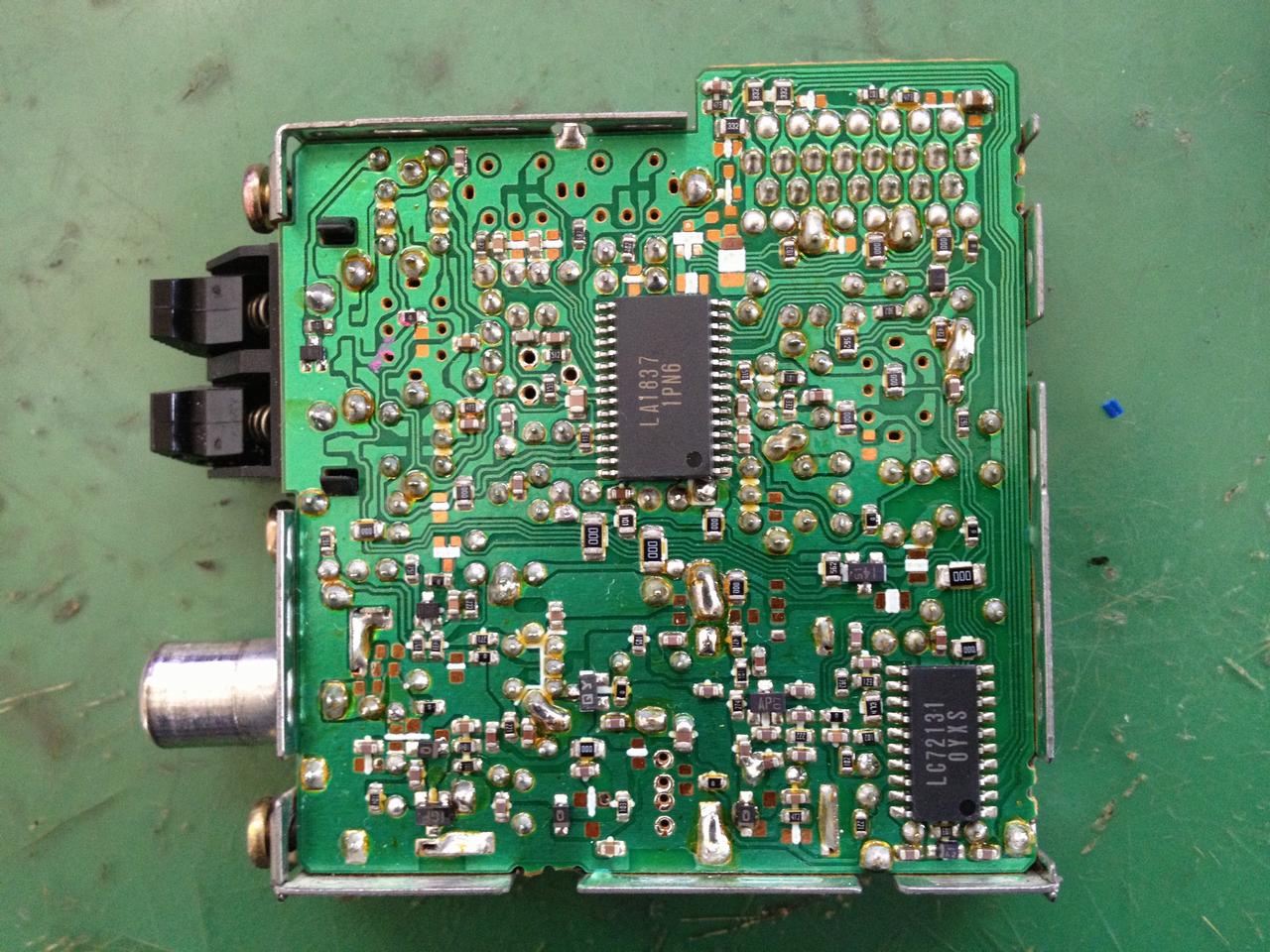
Signal names of the terminals of the tuner unit, i was able to know so easy had been silk printed on the main board of the mini component. In this, I am pulling out the only signal required for the production of this time.
From the name of the signal, it was found that it can be controlled by the serial from the microcomputer, but i willn't be able to write a program of microcomputer If i don't know the signaling protocol specific. Therefore, an exploded view of the tuner unit, and i have a look at the parts, "LA1837" and "LC72131" of SANYO products were used. I was able to make the program by data sheet of these IC's which were downloaded from the net by me.
2-2. microcontroller board
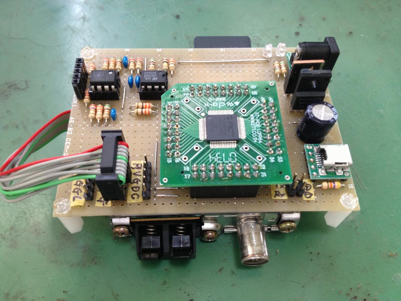
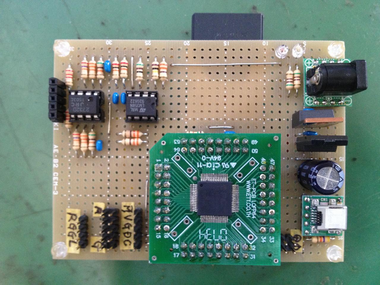
To be able to high-speed sampling of 44.1KHz some leeway, i used "PIC32MX695F512H" microcomputer which works at 80MHz clock. It is the PIC familiar with recent work here. I made the circuit on the universal board by using the LQFP converter board.
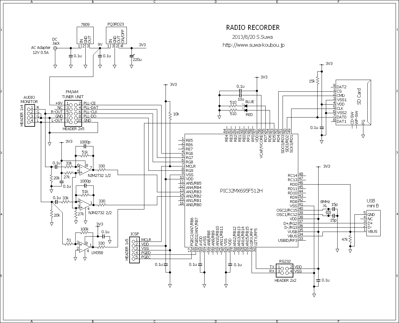
The microcontroller board which i made and the schematic are shown below.
 |
 |
 |
Because audio signal output level from the tuner unit was low a little, lightly amplified it by using operational amplifier which has name NJM2732. And it was level shifting output voltage. Output of the operational amplifier was connected to the analog input pin of AN2, AN3 of PIC.
Another operational amplifier which has name LM358 constitutes a comparator circuit. it converts into a pulse signal from the audio signal of the left channel. This pulse signal is used to detect JIHO signal(pi, pi, pi, pawn). It is read from RD5.
Control signal for setting the frequency of the tuner (PLL-xxx), instead of using the SPI module, i used the digital input/output pins from RG6 to RG9.
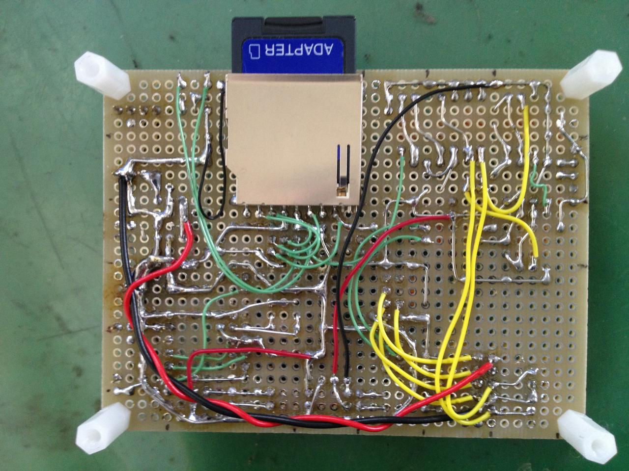
I have to control the SD card using SPI3 module. I didn't use a signal of write-protected detection and card detection signal of the SD card. These signals are set to writable with always inserted card in the program.
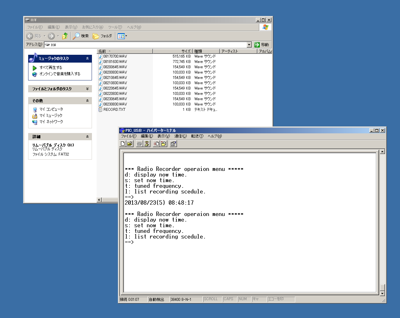 |
It's a composite device of CDC and MSD. Recording start time is made the file name. |
It was connected to a PC via USB in order to initial value setting of calender clock, or in order to reading of the recorded wav file, or in order to updating of file which has recording schedule. Microcontroller board is a composite device of MSD (mass storage) and CDC(communication class).
SD card is recognized by the computer as a removable disk. Moreover, if the COM port which made USB connection is specified directly and terminal software, such as a hyper-terminal, is started, the display and change of the present time inside a microcomputer can be performed from on a terminal screen. And frequency setting of a tuner can be performed.
In addition, UART2 terminal for a debugging output, the ICSP terminal for programming, and LED of the blue and red for operation monitors were installed. The voice monitor terminal was also prepared so that it could be checked whether the tuner is set as the target frequency. If headphone amplifier etc. are connected, the contents of reception broadcast can be checked.
Is about the power supply circuit. +9V is required for the operation of the tuner unit. +3.3V is required for a SD card and the PIC. When using the adapter of +9V, power supply IC was able to be managed with one piece. However, at hand, there is no adapter of +9V, and there were an adapter of +12V and a regulator IC of 7809. Then, it had power supply composition as shown in a circuit diagram.
3. Software
It was developed in C using the C32 compiler on the MPLAB IDE. Project files together completed are as follows.
-
Project files:RadioRecorder_20130829.zip
The main processings are explained briefly. For details, please refer to a source file.
Controlle of SD Card(ff.c mmc.c usb/msd.c)
The SD card can read and write data directly specifying the sector. But, in order to be able to access easily from the PC, in the same method as in previous work as "DriveRecorder", I used the FatFs of Mr. Chan created.
It is controlling using SPI3 module of PIC. If a SDHC card is used, it will read and write with a 20MHz clock.
Although the clause of the "microcomputer board" also explained, insertion detection of a card and write-protected detection are always set as card insertion and the state which can be written in within a program, without using.
Controlle of tuner unit(tuner.c)
I created program in conformity with the protocol specification which was written in the data sheet of LC72131 that was used in the tuner unit. Since it is a serial control i might want to use the SPI module. But it is slightly more complicated protocol. I controlled it by the digital i/o pins.
When it called 'Tuned' function with frequency as argument, i made that is now possible to set the desired frequency. AM and FM unified the unit of the frequency of an argument into KHZ. If it want to set to 85.1MHz, call as Tuned(85100).
Recording Schedule(schedule.c)
I have to be able to register up to 40 recording schedule. If it change the settings of MAX_RESERVE beginning of the source file, it can increase the schedule as long as it is allowed by the memory.
One schedule is structure as follows.
  struct schedule_t{
    unsigned long frequency;  // listening frequency
    char year;  // -1, 1-99
    char month; // -1, 1-12
    char day;   // -1, 1-31
    char wday;  // -1, 0-6(sun-sat)
    char bhh;   // recording start hour
    char bmm;   //     miniutes
    char ehh;   // recording stop hour
    char emm;   //     miniutes
  };
If '-1' is set to the value of the Year, month, wday and day, these item will always match.
For example, if set to the like { 85200, -1, -1, -1, -1, 6, 30, 7, 0 }, radio program of 85.2MHz is recorded 6.30 to 7.00 every day.
Next, if set to the like { 85200, -1, -1, -1, 0, 6, 30, 7, 0 }, recording is 6.30 to 7.00 every sunday.
If year, month, day are set, recording is at once only in that day.
The recording schedule is set in a text file stored in the root directory of the SD card called "RECORD.TXT". The description form and description sample of a file are as follows.
  #*** schedule plan order form
  #
  # format1  order one day
  #   freq yyyy/mm/dd hh:mm hh:mm
  #
  # format2  every week day
  #   freq wday hh:mm hh:mm
  #   freq wday-wday hh:mm hh:mm

  86500 2013/12/01 05:00 06:00   once recording of 86.5MHz, 5.00 to 6.00 on December 1,2013
  89900 2013/12/24 23:30 00:30   once recording of 89.9MHz, 23.30 on December 24,2013 to 0.30 on the next day

  85100 sat     07:00 07:50      repeat recording of 85.1MHz, 7.00 to 7.50 every saturday
  80200 sun     16:30 17:45

  83600 mon-fri 06:45 07:00      repeat recording of 83.6MHz, 6.45 to 7.00 on every monday to friday
  76500 mon-fri 08:30 08:40
  78500 sat-mon 01:20 01:35      repeat recording of 78.5MHz, 1.20 to 1.35 on every suturday to monday
When recording time overlaps, recording of a previous schedule is executed, but a next schedule does not record.
It compares the current Date and Time and the Date and Time of recording start scheduled in per minutes. if they match then start the recording process.
To open and read the "RECORD.TXT" file, I am using fgets() and fopen() functions. In order to access the SD Card using these functions, I created the low level functions.
Recording process(record.c)
Recording processing is performed as follows.
A tuner is set to the target frequency, A/D conversion result interruption is validated after that, and an A/D conversion module is started in an automatic sampling and an automatic conversion mode. Thereby, an interrupt occurs for every completion of conversion.
This interruption cycle adjusts sampling time and an AD translation clock so that it may be set to 44.1 kHz. It is 11.05us per channel. It set up and made it 22.1us (45.294 kHz) by conversion for two channels.
Although there was 2.7% of an error with 44.1 kHz, when the WAV file of the recording result was played with the personal computer, there was no audio sense of incongruity. Moreover, this was also satisfactory although sampling timing was shifted 11.05 us by the left channel and the right channel.
In interruption processing, an A/D conversion result is written in two or more buffers prepared on the memory one by one. One buffer has a size of 4096 bytes which can store two channels, 16 bits, and 1024 samples. These 16 buffers are prepared.
The A/D conversion result stored in the buffer writes out and goes to the file of SD card one by one, whenever one buffer fills.
Even in the process of writing to the SD Card, the interrupt handler, because it writes to the next free buffer, spillage of the A/D conversion result should not occur.
However, occasionally, spillage will occur. There seems to be when the time it takes to write to the SD card at the time, such as updating the FAT. The buffer, because there 16 buffer, its time allowance, is there (1024 * 15)/44100=0.348, also about 350msec, but it does not seem trivial at this.
It is possible to further increase the number of buffers in PIC32MX695F512H, because there 128KB of RAM, but decided to take a way as drastic measures, without extra processing, such as Fat update.
The sector was directly specified as some area of SD card, the A/D conversion result was once written out, they were read after the end of recording and how to return as a file of a Fat file system was considered.
As a result, missed data is now not occur, but the time for writing back to this after the end of recording is now required. I can no longer recording time are continuous for it.
Time adjustment by JIHO(jjydecord.c)
The adjustment of the time in the calendar clock, it was decided to use the JIHO. This method can be used to adjust the timing of every hour on the hour, but it does not allow to setting the date and time. I have to allow the date and time settings manually after startup. Connect it to PC using the USB, and set from the PC.
When it comes to 45 seconds every hour 59 minutes, receiving a radio broadcast of NHK, 30 seconds, perform the detection of JIHO signal. Detection JIHO signal has done by counting the number of pulse signals.
If the JIHO signal can be detected, to perform adjusting time, it does not do anything otherwise.
The initial setting time and date using the manual of the device after starting, you need to do to be within 15 seconds plus or minus while watching and radio clock. It is not possible to correct that it is not so.
That this adjustment process does not work during recording.