| Make a MZ-80 emulator by using PIC32MX | 2013.11.3 |
[Japanes][English]
1.INTRODUCTION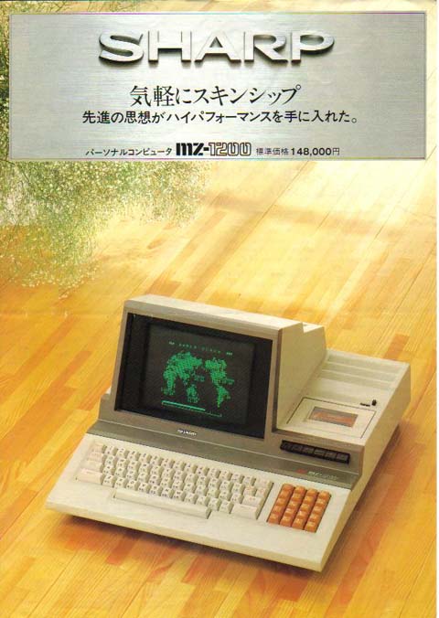 I used to have a MZ-1200 microcomputer which is an 8-bit microcomputer of Sharp Corporation. The MZ-1200 is the last version of MZ-80 series microcomputers, and I recall programming a basic compiler which supports integer type only for it.
Remembering those old days, I sometimes operate this compiler on the MZ-80 emulator in the Windows environment. About a month ago, I found a person who made a MZ-80 emulator only by using a PIX32MX on the Internet. Then I thought of making it too by myself.
About ten years ago, I made an emulator of the MZ-80 which runs in the Linux environment. At that time, I found an emulator for the MZ-700 called mz700em at an overseas site. I downloaded it, and made an emulator for the MZ-80 on the basis of the mz700em.
This time I would like to make a similar emulator using the PIC32MX.
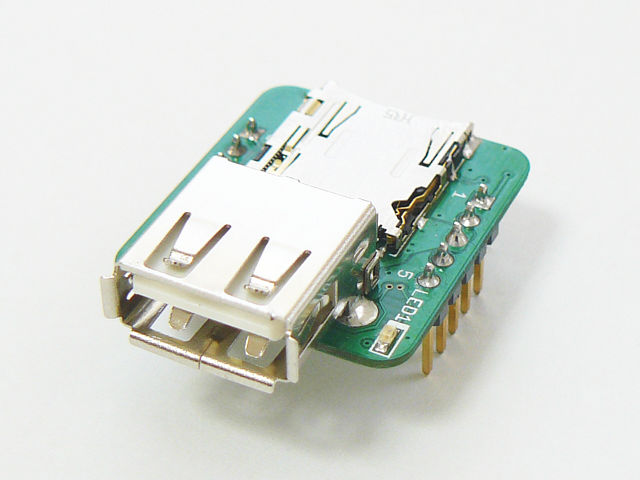 |
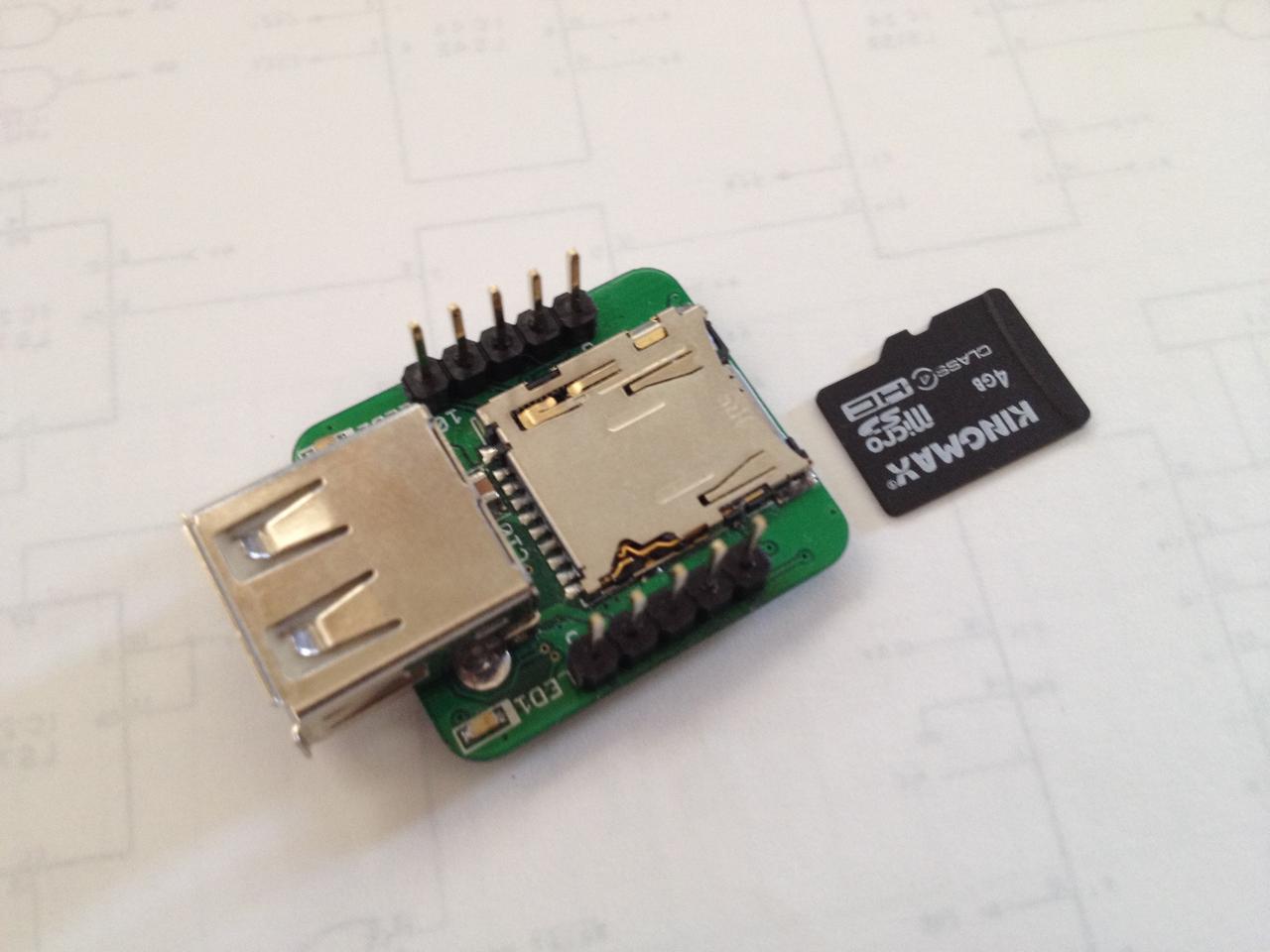
Despite its small size, the SBDBT32 is provided with a high-performance PIC32MX695F512H, a USB-A connector and a SD card slot. Although the I/O port looks conveniently usable, it has only ten pins. In addition, 5-pins or one half of them are assigned to the PICkit3 connection which also serve for power input. The remaining 5 pins are limited to the interface of the UART. [SBDBT32 schematic]
According to an example found in the Internet, only a few pins are actually required for the PIC32MX. The SBDBT32 can be connected to a TV if we can assign one pin to the sound output, and two pins to the NTSC composite signals (video and sync).
Normally cassette tape interface pins and keyboard connection pins will also be required, however, we can get rid of them by alternatively using a SD card and a USB keyboard, thanks to the SD card interface and the USB A connector provided in the SBDBT32.
In this way we can make an emulator using one SBDBT32 board and a few external resistors.
2. Specification of emulator
I determined specifications of the emulator as follows:
- To use a conventional TV set with NTSC signal input pins as a display.
- To use a USB keyboard for a PC. Because of the difference of key layout between a PC and the MZ-80, key codes are to be converted by a software program.
- To output sound signals directly to a small speaker.
- To store all MZ-80 software as files on a SD card which is FAT32 formatted. I will use the FatFs software module developed by Mr. Chan to access FAT32.
- Many program files are stored in the SD card. When 'Load' command is executed in the monitor program or in the Basic interpreter, a file list will be displayed on the TV screen, from which required file can be selected.
- To write a new program based on the one I created previously which runs in the Linux environment. It needs a new coding for handling the USB keyboard.
- To add a necessary processing to generate video signals, referring to the program found on the Internet.
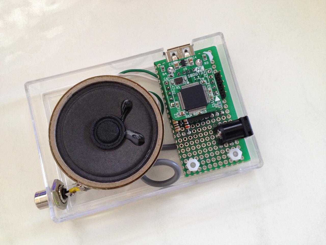
- To house the entire emulator in a small case together with a speaker, as it is composed of only one SBDBT32 board and a few resistors.
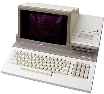 |
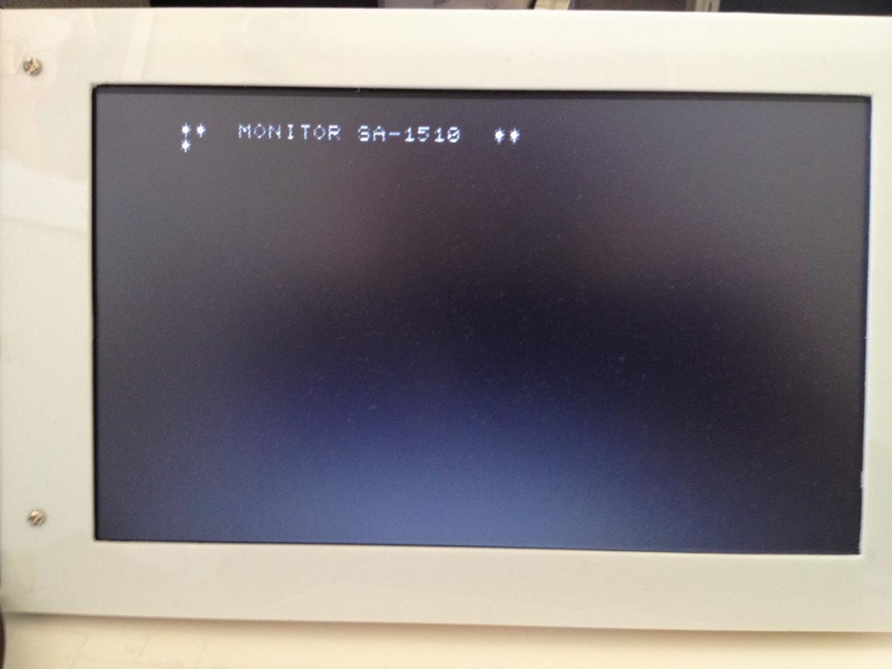
The MZ-80A is an overseas (outside of Japan) model of the MZ-1200. It supports hardware scroll, and can handle English small letters, naturally because it is an overseas model. The monitor program is SA-1510 rather than SP-1002 used in the MZ-1200, and the basic interpreter is SA-5510 rather than SP-5030.
In addition, I got the owner’s manual, the monitor program and the Basic interpreter of the MZ-80A, in the process of collecting information of the MZ-80. I would like to make an emulator which can emulate features of the MZ-80A.
The operating mode among the MZ-80A or MZ-1200 can be selected during the startup. When the MZ-80A is selected, the SA-1510 monitor program and CGROM for overseas will be loaded from the SD card. Otherwise, the SP-1002 monitor program and CGROM for domestic use will be loaded. Because the key matrix is also different depending on the mode selected, I will solve it by the software program.
3.Assign output pins and select a peripheral modul
3-1 Assign output pins
3 pin to be assigned from SBDBT32, can be selected from the 5-pin for the UART. Pins for the UART are as follows.
SBDBT32 connector terminal J3| pin 6 | RTS | --- | SCK3/U1RTS/OC2/RD1 | |
| pin 7 | TX | --- | SDO3/U1TX/RD3 | video signal |
| pin 8 | RX | --- | SDI3/U1RX/RD2 | |
| pin 9 | CTS | --- | U1CTS/RD9 | synchronization signal |
| pin 10 | STO | --- | RB9 | sound out |
Three pins are assigned for video, sound, and sync signals. As will be explained later, because sound output and sync signal are to be turned on and off in the interrupt routines of the timer module, they can be selected from any pins of digital output. On the other hand, the video signal needs to be assigned to pin 7(SDO3/RD3) as the generation of video signal uses the SPI module(SDO).
Pins 6, 7 and 8 are associated with the SPI3, and left unused except pin 7 which is assigned to the video signal output. As a result, I assigned pin 10 to the sound output, and pin 9 to the sync signal.
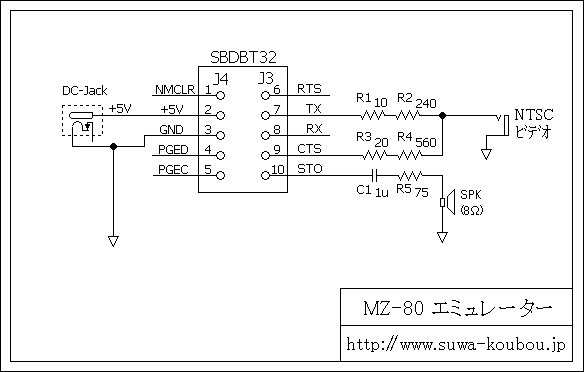
After assignment of necessary pins, I drew a schematic of the emulator. It is a simple circuit as shown Fig-1. I will explain the values of resistors in the schematic later.
3-2 Select a peripheral module
Peripheral modules of PIC32MX695F512H used in the MZ-80 emulator are as follows. Each modules work by using interrupt.
 |
| T1 | 1msec interval system timer | simulate of MZ-80 peripheral | |
| T2 | fall timing of NTSC sync signal | using RD9 as output | |
| T3 | generate sound | using RB9 as output |
SPI module
| SPI2 | SD Card interface | read and write the program of MZ-80 | |
| SPI3 | NTSC video signal | output video signal by transmitting interrupt |
OC module
| OC1 | rise timing of NTSC sync signal | using RD9 as output | |
| OC2 | start timing of NTSC video signal | control SPI3 transmit interrupt |
USB module
| U1 | HID driver | for handling USB keyboard |
4.How to use
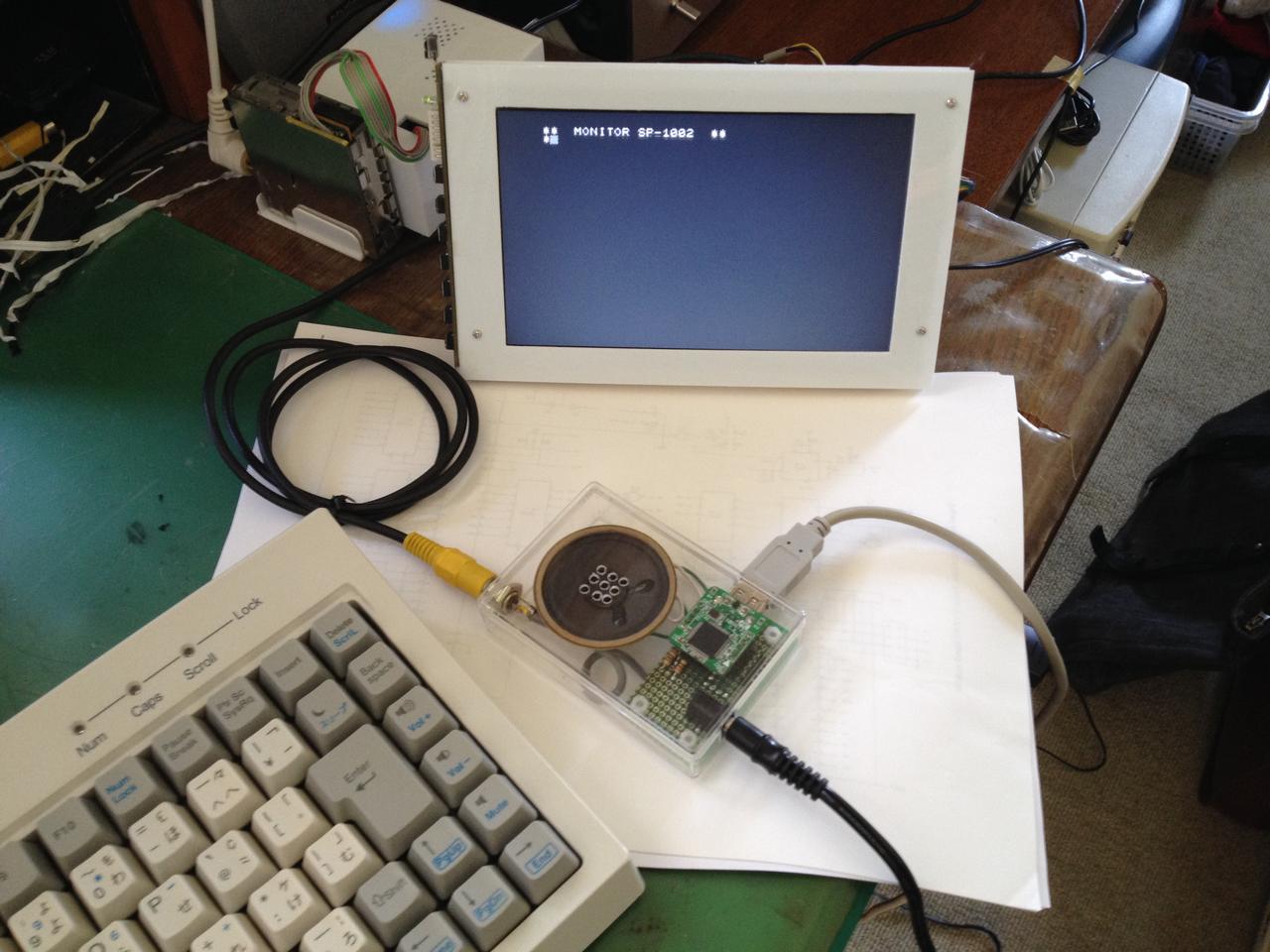
The completed emulator is shown in the photograph below.
The MZ-80 monitor program, CGROM data, game programs and Basic interpreter, which are required for the operation of the emulator are stored in the SD card as files.
File names of the monitor program and CGROM data shall be stored in the SD card with the following file names:
- English Version: SA-1510.ROM SA-CG.ROM
Japanese Version: SP-1002.ROM SP-CG.ROM
If any key is pressed right after turning on the power, the emulator starts up in the MZ-80A mode. After that, the monitor program SA-1510 starts up. If no key is pressed the MZ-1200 mode and the monitor program SP-1002 start up.
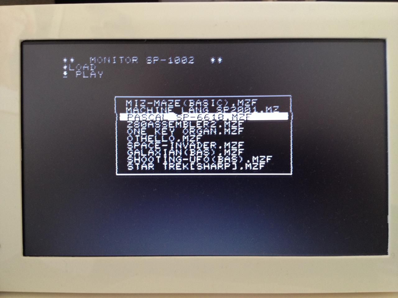
Run the LOAD command, and when the ↓ PLAY mark appears on the screen, press the function key 10. Then you can choose the program to be started from the file list on the SD card(extension is .MZF) which will be displayed in the center of the TV screen.
When the function key 11 is pressed while the emulator is running, the machine is reset. Since it resets the PIC32MX itself, the emulator will return to the state immediately after the power on. You can change the mode of operation at this time.
 |
 |
 |
| External pins of SBDBT32 were replaced to the connector side so that it fits in a small case. Programs of MZ-80 are stored in the SD Card. |
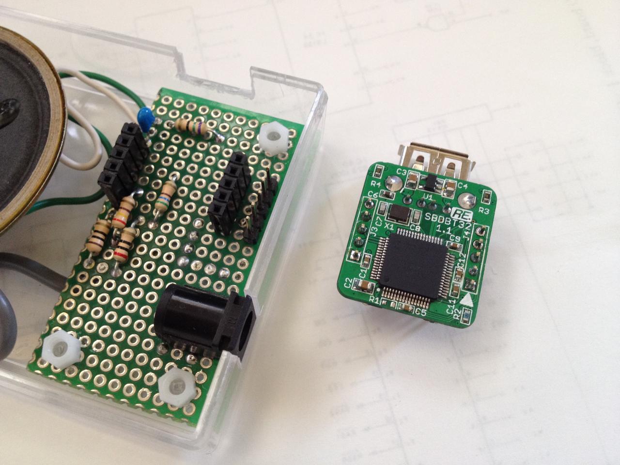
The SBDBT32 plugs into the universal board which is provided with a power connector and resistors. | The entire circuits were housed in a single small case together with a speaker and a video output terminal. |
 |
 |
 |
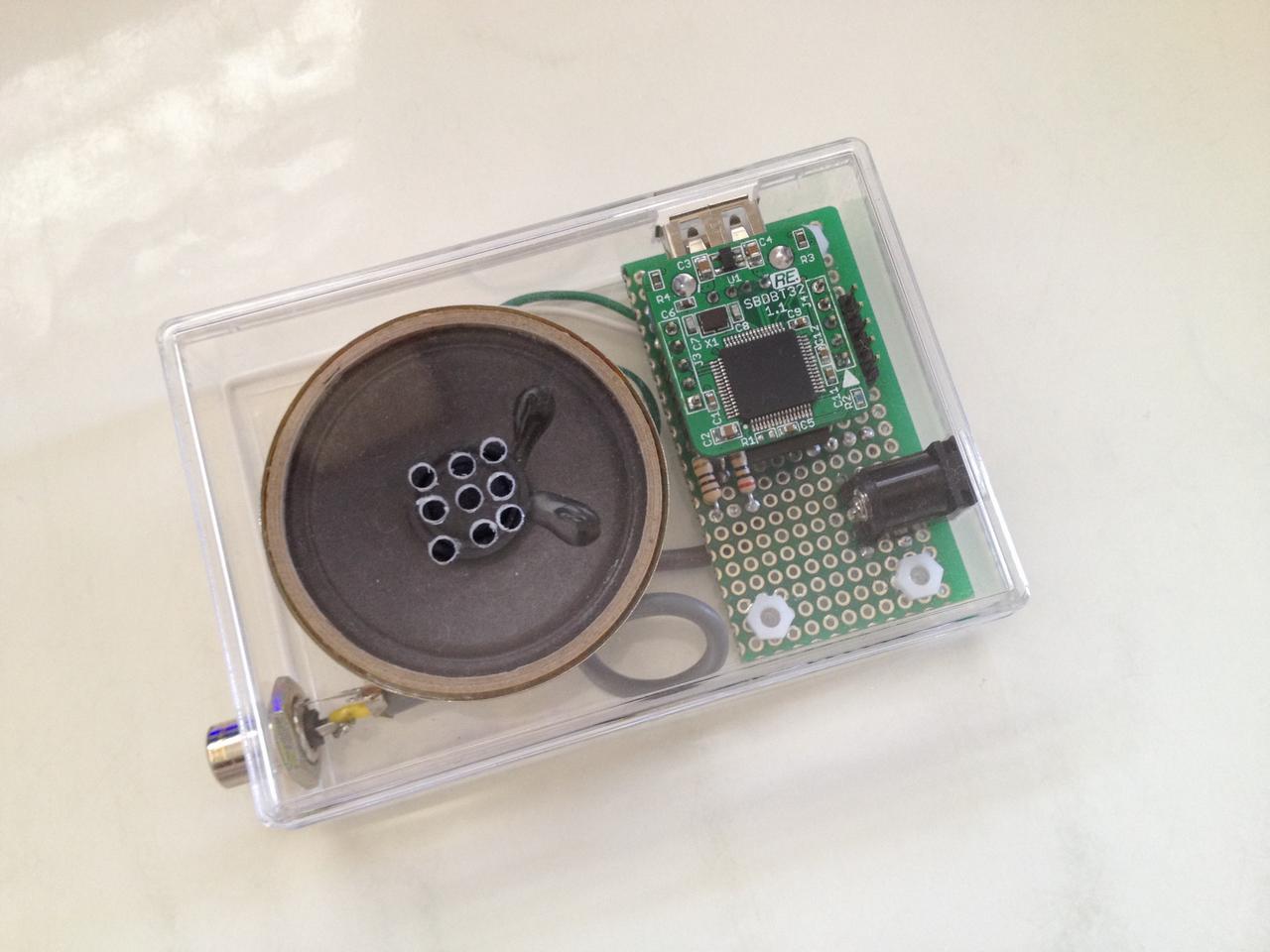
| It is completed by attaching the lid to the Case. I bought a see-through Case from the Akizuki Denshi. |
Under test connecting a power supply, a USB keyboard, and a LCD TV. | Run the LOAD command, then a list of files in the SD Card appears. |
 |
 |
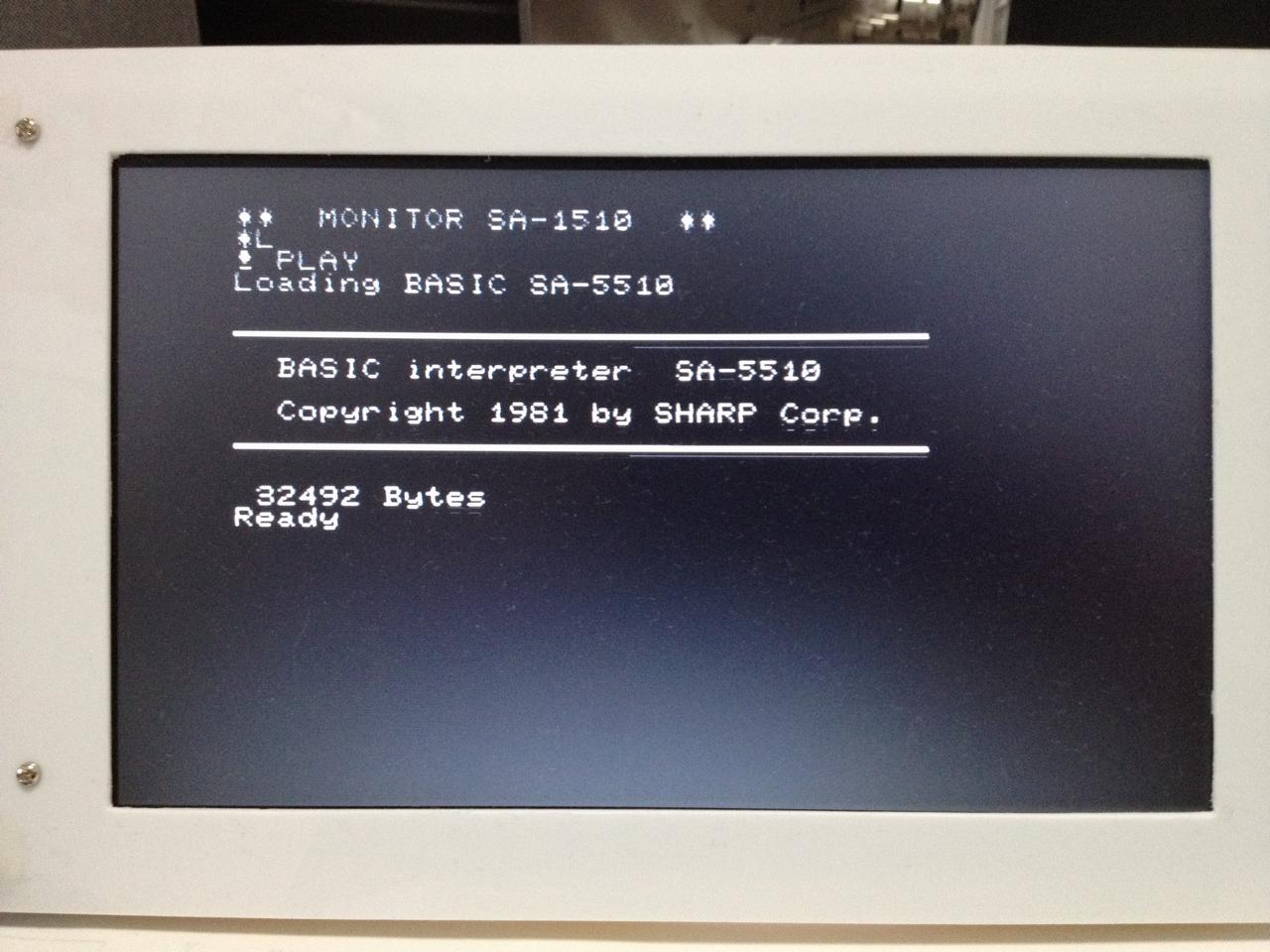 |
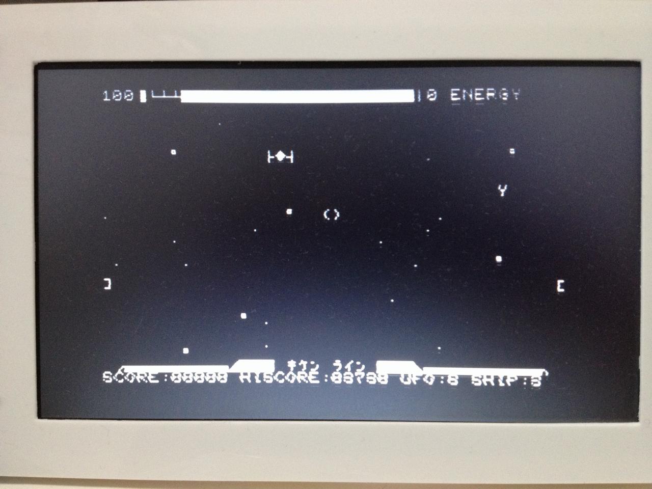
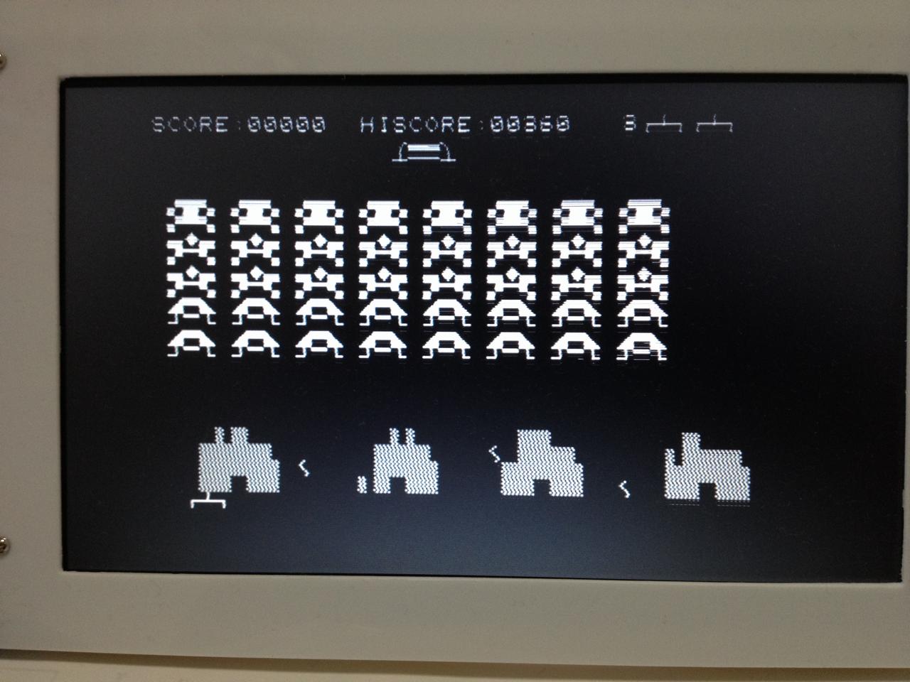
| STAR WARS game has worked well. | Monitor SA-1510 overseas version also worked. | Run a basic interpreter with the SA-5510 overseas version. English small letters are displayed. |
 |
 |
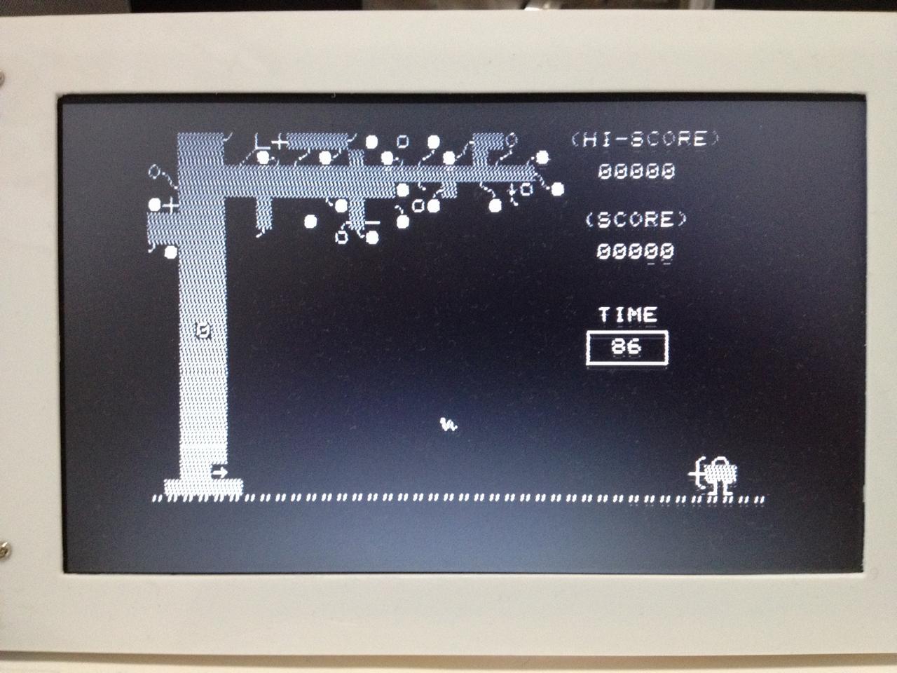 |
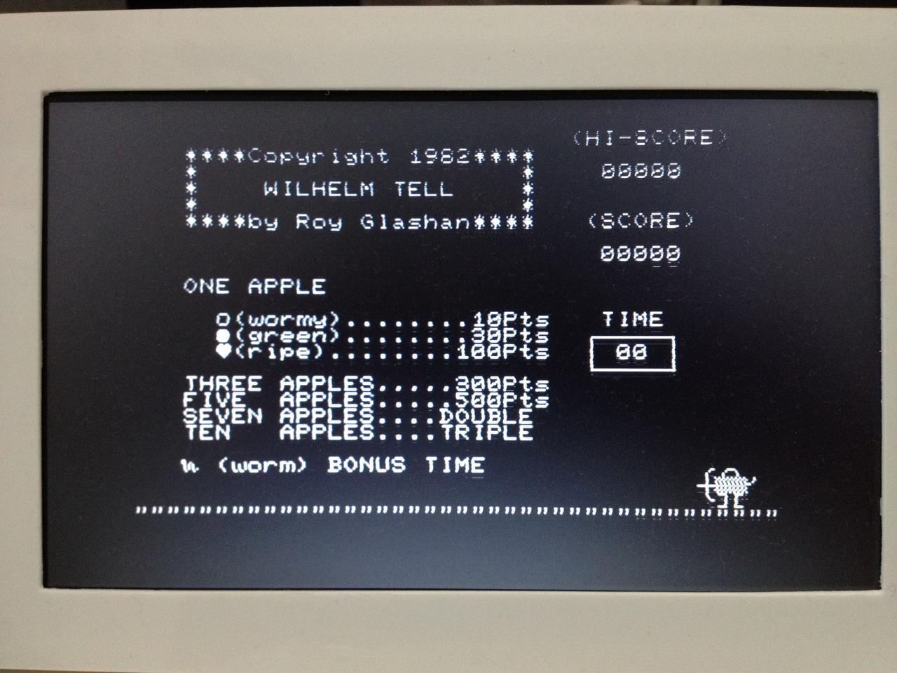
| Startup screen of the WILHELM TELL which is an overseas game. Game starts when by pressing the spacebar. |
It is a simple game just shooting falling apples by arrows. But I will be keen on it. |
5. Program of emulator
The following sections describe the program of the emulator which I made. I wrote source codes of all programs in C, using the C32 compiler on the MPLAB IDE version 8.92. You can download the project file stored at the following link.
-
Project File: mz80em_SBDBT32_20131102.zip
I will describe key points for each function below. For more information, please refer to the source program.
5-1 Simulated peripherals MZ-80(rtc.c,mz1200.c)
The MZ-80 is composed of the following peripherals;
A sound generator, a cursor blinking timer, a tempo timer for playing music, and a counter for clock.
The sound generator is made in such a way to generate sounds by toggling the RB9 pin in the periodic interrupt routine using the timer T3 module. While the actual machine generates sounds using 2MHz clocks, this emulator uses 2.5MHz clocks, because the clock of peripheral module is set to 80MHz. The difference is reconciled multiplying the division value of the emulator by 1.25 times of the one set in the actual machine.
The cursor blinking timer, tempo timer for playing music and the counter for clock are simulated using the timer T1 module. Specifically, interrupts of the T1 occur in 1msec interval, and toggle the value or count down the value of each timer variable.
The cursor blinking timer toggles the variable values every 500msec. The tempo timer for playing music generates a tempo frequency of 100Hz by toggling the timer every 5msec. The counter for clock is counted down every 1sec.
5-2 Keyboard emulation(keyboard.c, key.c)
I made the program for handling a USB keyboard utilizing a sample program of Application Library that Microchip offers. In addition, I have removed the unnecessary portion for the emulator.
Each key is read by the interrupt of the T1 timer every 10msec. The key matrix is set to convert the USB key codes that have been read, as if the appropriate keys of the MZ-1200 and MZ-80A have been pressed.
Since the key matrix is different between the MZ-80A and MZ-1200, I made a converting table for each machine.
5-3 Emulate of Z80 CPU instruction(z80.c)
The program that emulates the instruction of the Z80 CPU has been made slightly modifying the source file that I made previously for another emulator. It was originally an emulation program of the Z80 CPU in the MZ-700 emulator 'mz700em' for Linux. While the original source codes were written to process instruction codes of the Z80 for branching by switch statements, I have totally modified them to branch using a function table.
For emulated instruction codes of the Z80, I have adopted the original codes, although frequently used macros in the original source codes have been replaced with the results of the expansion of the macros.
Four undefined instruction codes, from 0xEDFC to 0xEDFF, have been assigned to the read and write processing of the cassette tape (or the SD card file). When the emulator starts up, the monitor program is loaded from the SD card into the RAM area, and the first two bytes of the entrance part of the reading and writing routine in the monitor program will be replaced with these undefined instruction codes.
In order to emulate the execution speed of the actual machine which is based on the 2MHz clock, I adjusted the timing using the timer T5 which operates at 2.5MHz.
I remember that when I played the 8-QUEEN with a Basic compiler using an actual machine mentioned in the introduction, it required 90 seconds. It was 85 seconds using the emulator which I made this time. I believe that the difference is small enough. I felt comfortable using it, even when playing shooting games.
5-4 Reading and writing SD Card(fselect.c,mzfile.c,unixio.c)
When Load command is executed, the file list is displayed on the screen. This file list is made by searching files having only a file extension .mzf in the root directory of the SD card at starting up of the emulator.
The list of file names is directly written in the RAM area, after converting the character codes of the file name to display codes of the MZ-80A/MZ-1200. During the file selection operation, the key reading process of 10msec interval is suspended.
I used the unixio.c. for this project to read and write files on the SD card, so that the source codes I have written in the past for Linux (low-level I / O functions such as open, close, read, and write) can be reused as they are.
Numbers, common symbols and uppercase English letters of the MZ-80 are consistent with the standard ASCII character codes, however, Japanese kana and English lowercase letters are not. Therefore, file names created with the SAVE command of Basic interpreter and stored in the SD card will be garbled when the SD card is read in the Windows environment. The reverse operation causes the same problem. So, I have added a converting process between the MZ-80 and the standard ASCII character codes.
5-5 Generate NTSC video signal(video.c)
As for the generation of NTSC composite video signals, I took an advantage of utilizing the program of "The oscilloscope using a NTSC video output" which was introduced in "PIC24F application example" page in the laboratory of electronic work of Mr. Gokan Tetsuya.
Minor modifications have been made to fit the program to the SBDBT32, and to have the SPI3 module transmit 32-bit signals toggled by the sending interrupt. Further, processes for emulating hardware scroll of the MZ-80A and handling reverse screen display have been added.
The synchronization signal and the equivalent synchronization signal generated by this program are simple, but work well.
The clock frequency of the SPI module to generate video signals has been determined as follows.
The horizontal synchronization signal is 15.72kHz, or 63.6usec per cycle. Considering 4.7usec for the synchronization signal, 4.7usec for starting the video signal, and a free time of 1.5usec at the end of the signal, the video signal generation time turns out to be maximum 52.7usec.
The horizontal resolution of the MZ-80 screen is 320 dots because it accommodates 40 characters per line, which corresponds to 52.7usec/320 = 164.7nsec per dot, or 6.07MHz in the frequency domain. So, the clock frequency of the SPI3 module shall be set to 6MHz or more.
Since the clock frequency of the peripheral module is 80MHz, the SPI3 clock can be chosen among 40MHz, 20MHz, 13.33MHz, 10MHz, 8MHz, 6.66MHz, 5.7MHz, 5MHz, etc. This time I tested two frequencies, 8MHz and 6.66MHz, and chose 8MHz because the 6.66MHz made the display horizontally stretched on the TV screen.
Assuming a TV’s video terminal with 75 ohm input resistance, external resistance circuits for mixing the video signal and synchronization signal have been designed with a 250 ohm resistor in the video signal side, and a 580 ohm resistor in the synchronization signal side. The voltage values are calculated to be as follows, considering the PIC32MX output voltage of 3.3V.
-
White Level - 0.99v Black Level - 0.299v Syncronization signal - 0v
Since I did not have resistors with these values in my hand, I ended up using four resistors as shown in the circuit diagram. Although I have not verified, the allowable range of the TV side is large enough, so that 240 ohm and 560 ohm resistors would probably work just as well.
6. CONCLUSION
The display quality of the TV screen is not really high, haunted by flickers. It may be caused by the unstable interrupt timing for generating the video signal and the synchronization signal, although I have not fully investigated the case.
Even so and knowing the advancement of technologies, the fact that an old computer could be easily reproduced in a small PIC microcontroller still impresses me.
I have released an emulator program this time, but did not release other programs such as CGROM, monitor programs, basic interpreter and games, as they are the works of Sharp Corporation or other authors. Kindly obtain them by yourself to play with this emulator.